
Infrastructure sector
Overhead Transmission Lines: Towers, Sag–Tension & Foundations
AC overhead transmission line engineering up to 765 kV: conductor, earth-wire and OPGW selection, sag–tension and stringing charts, route plan and profile, tower spotting and schedule, single and double circuit tower design, and tower foundations, prepared to each project’s loading criteria and tower schedule.
Scope
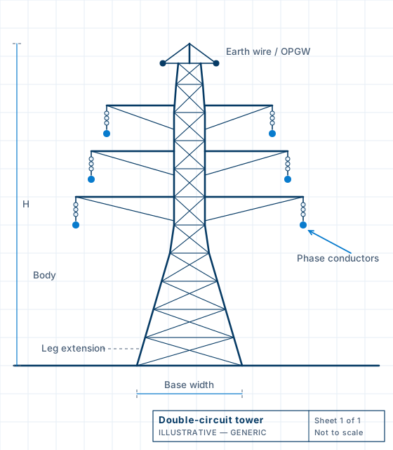
Transmission line engineering covers the line’s electrical design, the towers that carry the conductors and the foundations that carry the towers. CoreGrid works on AC lines up to 765 kV, including single circuit (SC) and double circuit (DC) tower structures, line terminations, and body or leg extensions where the project allows them. It is one of our engineering pillars, alongside substations and renewable and storage infrastructure.
Tower families are defined by each project. Where a specification refers to Type A, B, C and D towers, the applicable line angle ranges, span limits and loading are those in that project’s own tower schedule. We never assume a fixed angle classification. The design stage CoreGrid takes on, from tower geometry and analysis through detailing to foundation design, depends on the contract.
- SC and DC tower structures
- Line terminations and transmission tower systems
- Type A/B/C/D families as defined by the project tower schedule
- Body and leg extensions
- Design stage as agreed in the contract
Line electrical design
The line’s electrical design comes before the towers. Conductor selection balances current capacity, losses and cost, and is checked for corona and radio interference at the line voltage. Earth wire or OPGW is selected for fault duty and shielding, and insulation and clearances are set from the voltage, the pollution level and the project criteria. These choices fix the loads and geometry the tower design then works to.
- Conductor, earth wire and OPGW selection and sizing
- Losses, corona and radio interference checks
- Insulation, creepage and electrical clearances
- Shielding and lightning performance inputs
- Line entry interface with substations
Transmission Line Sag–Tension & Stringing Charts
Calculation for overhead lines, kept apart from substation busbar calculations.
This is the line calculation: Overhead Transmission Line Conductor Sag–Tension Analysis & Stringing Chart Preparation. For the phase conductor and the earth wire or OPGW, sag and tension are calculated under the specified temperatures and weather cases, with initial, final and creep conditions as applicable. The results are converted into stringing charts for the erection team, and they feed tower loading and clearance checks.
It is a different calculation from the substation work. Flexible busbar sag–tension and busbar short-circuit force (SCF) belong to the electrical design calculations and use different methods. PLS-CADD is the software listed for line profiling, tower spotting and sag–tension; its availability for a contract is confirmed at enquiry.
- Conductor, earth-wire and OPGW data and selection
- Sag and tension under temperature and weather cases
- Initial, final and creep conditions, as applicable
- Stringing chart preparation
- Clearance checks against the line profile
- Hand-over to tower loading trees
Inputs the design needs
Design starts from the client’s criteria and route data, which CoreGrid does not generate itself.
| Input | Why it matters |
|---|---|
| Voltage and circuit arrangement | Sets cross-arm geometry and clearances |
| Phase conductor, earth wire / OPGW data | Gives wire loads and attachment arrangement |
| Wind and loading criteria, reliability class | Drive the load trees and member design |
| Tower family and angle classification | Defines which tower types exist and their limits |
| Ruling spans, terrain and route profile | Determine tower heights, extensions and loads |
| Soil and geotechnical data | Needed for foundation type and design |
| Electrical clearances and insulator geometry | Fix the outline and cross-arm dimensions |
Tower structural calculations
Tower design calculations begin with the load trees and load cases: tension, suspension, transverse, vertical and longitudinal loads, with broken-wire and construction cases where the specification requires them. Steel members are then sized, bolted connections are designed, and foundation reactions and the weight and material estimate follow from the analysis.
Each load case and its source in the criteria are recorded so that a reviewer can see what governs each member group, and so that a change in the criteria can be traced to the members it affects.
- Load trees and load cases
- Tension, suspension, transverse, vertical and longitudinal loads
- Broken-wire and construction cases, where required
- Steel member sizing
- Connection and bolt design
- Foundation reactions
- Weight and material estimate
Tower drawings
Tower drawings turn the analysis into documents others can use. The outline and geometry drawing defines the silhouette, panel layout and cross-arm dimensions. Attachment and insulator configuration drawings show how conductors and earth wires connect, and the clearance diagram shows electrical clearances to steelwork. Member and connection details, assembly and fabrication drawings and bolt lists are provided where they are included in the scope.
Route plan, tower spotting and tower schedule
Route work is handled alongside the tower design: route selection and optimisation, survey review, the route plan and profile, tower spotting, the tower schedule, and ground and crossing clearance checks. These are taken on where the contract includes them; where survey data come from the client or a surveyor, our checks depend on their accuracy.
Site supervision, inspection and commissioning support for lines are available as separately contracted site support.
- Route selection and optimisation, where in scope
- Survey data review
- Route plan and profile, tower spotting and profiling
- Tower schedule and tower families
- Ground and crossing clearance checks
- OPGW, earth wire and earthing interfaces
Tower foundations
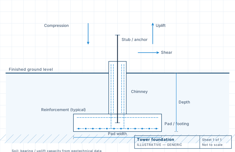
Tower foundations are designed for the soil classes in the project. Typical arrangements are pad-and-chimney footings, piles, rafts or other approved types, selected for the actual project conditions. Design covers uplift, compression, shear and overturning, using the reactions from tower analysis and the geotechnical data. Outputs are RCC foundation drawings and reinforcement schedules.
Foundations are designed together with the tower so that stub setting, anchor details and reactions agree. Related civil foundation work for substations is described on the civil and structural page.
Typical deliverable package and design stages
| Stage | Typical content | Typical output |
|---|---|---|
| 1. Criteria and family | Confirm loading criteria, conductor data, tower family and clearances | Tower design basis report |
| 2. Loads and analysis | Load trees, load cases, structural analysis | Analysis and member checks |
| 3. Members and connections | Member sizes, bolts, weights | Member list, weight list, connection design |
| 4. Drawings | Geometry, attachments, clearance diagram, stub setting, fabrication and erection drawings | Tower drawing set and tower schedule |
| 5. Foundations | Foundation design for soil classes | Foundation calculations, drawings, schedules |
Stages are taken on as the contract defines. Tower, line and civil interfaces (loads, stub details and clearances) are coordinated through the same document register. Statuses follow the project’s own convention.
Related
Share your tower schedule, loading criteria and soil data
Send the tower schedule, loading criteria, conductor data and the soil information you hold. We will confirm the design stage and deliverables that fit your contract.