
Discipline · detailed engineering
Electrical Design & Engineering
AIS/GIS substation electrical engineering up to 765 kV, applied also to renewable pooling substations, solar and wind plants, BESS connections and the AC side of HVDC stations. Drawings, design calculations, studies and schedules are kept apart, as a design package keeps them.
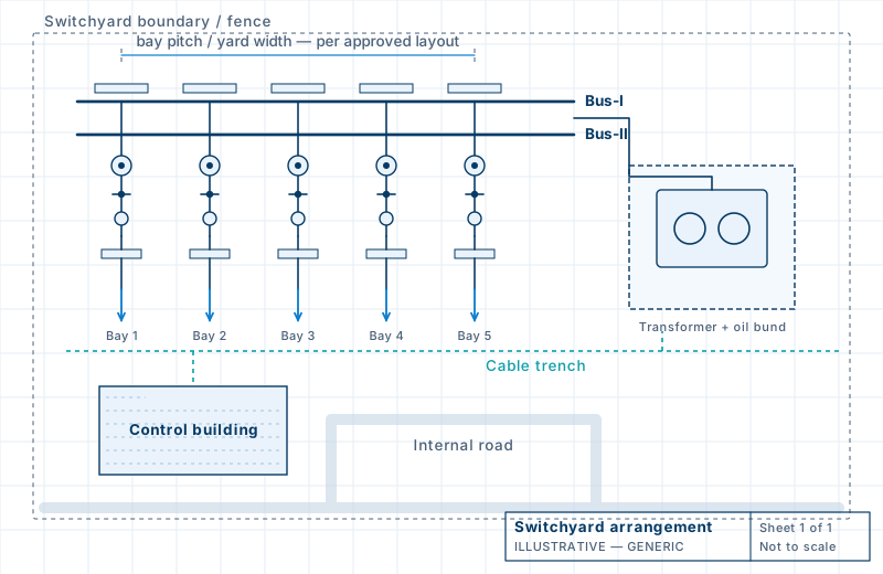
Scope and design basis
Electrical detailed engineering is the stage at which a tender or basic design becomes drawings and calculations that suppliers and site teams can build from. CoreGrid prepares it for AC voltages up to 765 kV, whether the work is a greenfield switchyard, a pooling substation for a renewable plant, a BESS connection or an extension to an existing station, as each package defines.
The design basis comes from the project’s own documents: the single line diagram and utility criteria, fault and insulation levels, statutory clearances, equipment GTP and drawings, soil information where earthing or foundations depend on it, and the master drawing list (MDL). Where an input is missing we say so, record the assumption we propose and ask the client to confirm it. Loads, levels and positions pass to civil and structural design as controlled interface data.
Inputs the design depends on
| Input | Why it matters |
|---|---|
| Single line diagram, bay list, utility criteria | Define the bus scheme, bays and ratings |
| Fault levels and insulation levels | Drive conductor, earthing and clearance design |
| Technical specification and MDL | Set deliverables, formats and codes |
| Vendor GTP and drawings | Fix dimensions, weights and terminal loads |
| Soil resistivity data | Needed for the earth grid and foundations |
Section 01
Electrical Engineering Drawings
Drawings first, beginning with the Single Line Diagram.
Drawings come first because they fix how the yard is arranged and connected. The Single Line Diagram (SLD) shows the bus scheme, bays, feeder and transformer connections and ratings. The Overall General Arrangement (GA) and the electrical layout plan and sections place the equipment on site so that bus levels and clearances can be checked. The Erection Key Diagram (EKD), in plan and section, identifies the equipment and fittings of each bay for erection; its content and format follow the client’s specification.
Protection, control and SCADA drawings are included only where the contract assigns them: protection and control schematics and SAS–SCADA interface drawings. Detailed vendor panel manufacturing drawings are not assumed to be prepared by CoreGrid.
Diagrams
- Single Line Diagram (SLD), bus scheme and bay configuration
- Protection and metering SLD, where in scope
- LT AC and DC auxiliary system SLDs, with battery, charger and DCDB interface
- Control and protection schematics / SAS–SCADA interface drawings, where part of the contract
Layouts
- Overall General Arrangement (GA) / switchyard GA
- Electrical layout plan and sections, bay elevations, equipment positions and electrical clearances
- Erection Key Diagram (EKD): plan and section
Earthing, lightning, cables and lighting
- Earth mat layout / earthing grid layout, with equipment earthing and bonding details
- Direct Stroke Lightning Protection (DSLP) layout
- Power and control cable routing layouts, cable trench layout, cable block diagram
- Indoor and outdoor illumination layouts
Section 02
Electrical Design Calculations
Sizing and design checks. Transmission line sag–tension is a different calculation and sits on the transmission lines page.
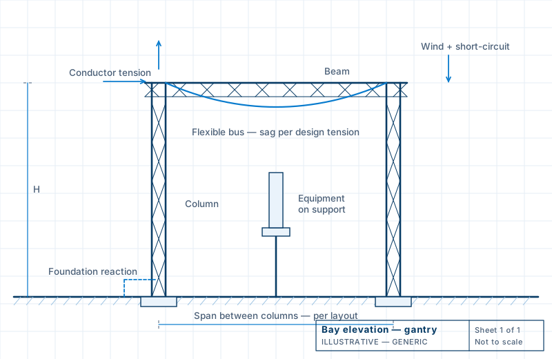
Calculations are separate from drawings and from system studies. Conductors and busbars are selected for current, temperature and fault withstand. For flexible buses the sag–tension calculation fixes how the conductor hangs and what tension it passes to gantries and terminals. The short-circuit force (SCF) calculation is a mechanical, electrodynamic check on conductors, spacers, insulators and supports, and its results become loads for structure and foundation design. It is not the short-circuit (fault level) study, which is a network study listed under studies.
Earthing design starts from measured soil resistivity and the fault current and duration the grid must carry. We size conductors, calculate grid resistance, ground potential rise (GPR) and step and touch voltages against the project limits, and model non-uniform soil in SES-CDEGS where the project needs it. We do not promise a target resistance before the calculation is complete. DSLP is calculated by the project’s chosen method and then drawn as a layout.
Conductors and busbar
- Conductor and busbar sizing / selection (current, thermal and short-circuit criteria)
- Flexible / strung busbar sag–tension
- Busbar short-circuit force (SCF) and critical span, mechanical support load check
Earthing and lightning
- Earthing system / earth grid design: soil resistivity, conductor sizing, GPR, step and touch potential
- Direct Stroke Lightning Protection (DSLP) calculation
Equipment and auxiliary systems
- Equipment rating and selection; CT, VT / CVT burden and sizing
- Neutral grounding resistor (NGR) sizing, where applicable
- Station battery sizing (220 V / 48 V or specified) and battery charger sizing
- Auxiliary LT AC/DC load calculation; auxiliary transformer, UPS and DG sizing where contracted
Cables, lighting and settings
- Power and control cable sizing, voltage drop and short-circuit withstand
- Indoor and outdoor illumination design calculation (DIALux evo)
- Relay setting calculations / setting sheets, where contracted
Section 03
Power System & Protection Studies
Power system and protection studies answer questions about the network rather than about one piece of equipment. They are prepared or reviewed as each project commissions them, from the client’s system data, and each proposal states the basis. Relay setting sheets follow from the protection coordination study and are listed with the design calculations, so the two are not counted twice.
- Load flow / power flow study
- Short-circuit / fault level study
- Insulation coordination study
- Harmonic analysis / harmonic load flow study
- VFTO study for GIS, where appropriate
- Switching transient / transient overvoltage study, where required
- Protection coordination / selectivity study
- Reactive power compensation / voltage regulation study
- Grid interconnection study for renewable, pooling and BESS, as contracted
Section 04
Schedules, Quantities, Document Control & Technical Review
Schedules, quantities and document-control items support the drawings and calculations. They are listed apart from them and are never sold as drawings. The master drawing/deliverable list (MDL), bills of quantities, GTP and vendor drawing review sheets and the comment resolution sheet (CRS) belong here.
Schedules and lists
- Power and control cable schedules and cable termination schedules
- Equipment and load lists
- Engineering design basis / criteria and interface documents
- Calculation and drawing registers
Quantities, control and review
- Master drawing / deliverable list (MDL)
- Erection BOQ, overall BOQ and quantity take-off
- GTP and vendor drawing review
- Comment Resolution Sheet (CRS)
Electrical engineering by infrastructure type
| Infrastructure | Electrical focus |
|---|---|
| AIS/GIS substations | Bus schemes, yard and hall layouts, SCF, earthing, DSLP, equipment ratings, auxiliary systems |
| Solar, wind and hybrid plants | Plant and collector SLDs, inverter and transformer interfaces, cable sizing, plant earthing, evacuation scheme |
| Pooling substations | Collector bay scheme, pooling transformers, GA and sections, Erection Key Diagram, metering, utility protection and SCADA interfaces |
| Battery energy storage | MW/MWh sizing basis, PCS and transformer interfaces, eBoP SLD, auxiliaries, protection, EMS/SCADA interface |
| Transmission lines | Conductor selection, losses and corona, clearances, line entries into substations |
| HVDC stations | AC switchyard and filter yard layouts, converter transformer yard interfaces, station earthing |
How we execute electrical engineering
Project SLD and criteria
Confirm the single line diagram, design criteria and deliverable list.
Coordinated GA and layout
Develop the general arrangement from approved equipment arrangement and clearances.
Equipment data verification
Check vendor data for dimensions, weights, ratings and terminal loads.
Technical calculations
Prepare calculations with traceable inputs and stated limits.
Drawing issue
Issue drawings with revisions, transmittals and register entries.
Electrical-civil interface checks
Check loads, levels and positions against civil and structural design.
Internal design check
Independent check of calculations and drawings before submission.
Client review
Submit for approval and respond to comments through the CRS.
Close CRS and final issue
Revise, close comments and issue in the status the project defines.
Each stage ends with a hand-over that can be checked against the MDL. “Issued for approval” differs from “approved” and from “issued for construction”, and we use those terms as the project defines them.
Submitted for the client’s or consultant’s review. It is a proposal for acceptance, not an approved document.
The formal response of the approving party, which may carry comments. Only the client, owner’s engineer or consultant can give it.
Released for use at site, in the status and under the convention the project defines. Revision labels differ between projects.
Related
Share your SLD, technical specification or MDL for an engineering proposal
Send us the tender extract, single-line diagram, master deliverable list or the specific calculation you need. We will confirm scope, inputs and a realistic submission sequence before any work starts.