
Discipline · detailed engineering
Civil & Structural Design & Engineering
Structures, foundations, buildings and site works for substations, pooling stations, solar and wind plants, BESS sites, HVDC station yards and transmission towers, designed from the approved layout, equipment loads and geotechnical data. Calculations and drawings are kept apart.
Design basis and information inputs
Civil and structural design depends on information from several directions, so the first step is to list what is needed and who supplies it. We work from the approved general arrangement or layout; the wind and seismic criteria the client specifies; the geotechnical report with bearing capacities and founding levels; architectural and building requirements; equipment terminal loads and dimensions; anchorage and foundation reaction schedules from vendors; the structural codes and utility requirements the project names; and drainage and grading constraints for the site.
Inputs that are missing or still preliminary are recorded in an interface and input register with the date each is needed. Design is not advanced on unconfirmed data without the assumption being written down and agreed. Coordination with the electrical design is by controlled interface data, and approvals remain with the party the contract names.
| Input | Typically from |
|---|---|
| Approved layout and GA | Electrical design |
| Wind and seismic criteria | Client specification |
| Bearing capacity, founding levels | Geotechnical report |
| Equipment loads and dimensions | Vendor drawings, GTP |
| Building requirements | Client, architect, services |
| Survey levels, plot plan, drainage constraints | Site survey, client |
Section 01
Civil & Structural Design Calculations
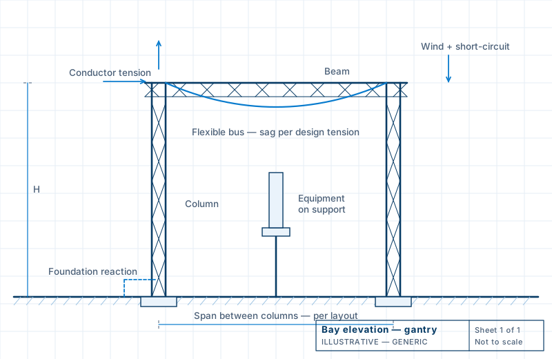
Calculations come first and drive the drawings. Switchyard structures carry conductors, equipment and lightning protection, so loads from the electrical design (conductor tensions, equipment weights and terminal loads, wind and, where relevant, short-circuit forces) are combined into load cases under the project code. We size members and connections, design bolting and base plates, and prepare analysis models for review.
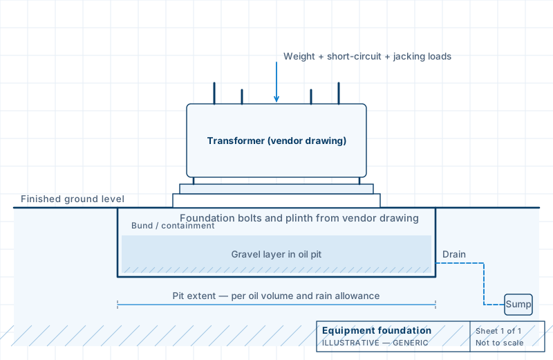
Footings and pedestals are designed for bearing, uplift, overturning and sliding against the allowable soil pressures in the geotechnical report, with anchor bolts and embedments designed with the foundations. Foundation bolt positions and oil pit dimensions follow the approved vendor drawing, which is why vendor data are verified before foundation drawings are issued.
Structures
- Switchyard gantry, portal / beam, bus support and equipment support structure design and analysis, with structure loading and reactions
- Lightning mast and shield-wire support design
Foundations
- Equipment foundations and foundation design: CB, CT/CVT, isolator, LA, transformer / reactor and GIS as applicable
- Anchor bolts, base plates and load combinations; geotechnical bearing considerations
Buildings and containment
- MCR / control room building (CRB), GIS hall and relevant plant-building structural design
- RCC design
- Transformer / reactor oil pit, fire wall, cable trenches and relevant civil structures
Lines and renewable sites
- Transmission line tower and tower foundation structural calculations, with the soil classes when contracted
- Renewable and BESS site structures and foundations as relevant: inverter, IDT, PCS, battery container, turbine interface
Section 02
Civil & Structural Engineering Drawings
Drawings turn the calculations into documents that fabricators and contractors can use. Where fabrication and erection drawings are assigned, they are produced from the same analysis model so the drawings match the calculation. Building services such as HVAC, fire protection and plumbing are designed by their specialists; we take their requirements as inputs and coordinate openings, loads and supports.
All drawings are checked against the electrical layout, so that a trench does not cross a foundation and a road does not leave a transformer without access for delivery or maintenance.
Structures
- Switchyard gantry / steel structure GA
- Fabrication, member, connection and erection drawings
Foundations and RCC
- Equipment, transformer and reactor foundation layout and detailed drawings
- RCC reinforcement details
Buildings
- Control room / MCR / GIS hall architectural and structural GA and RCC details
Site and infrastructure
- Cable trench, duct bank, road, drainage, grading, fencing and boundary wall drawings
Lines and renewable sites
- Tower GA, tower detail / fabrication drawings, tower foundation layout and reinforcement
- BESS and renewable infrastructure equipment foundation and site-civil drawings, where in scope
Section 03
Schedules, Quantities & Documents
Quantities and document control are not drawings or calculations, and are listed apart from them. Quantities are estimates from the issued drawings, not measured work.
- Civil BOQ and material take-off
- Bar bending schedules (BBS)
- Civil master drawing / deliverable list (MDL)
- Interface and input register
- Structural calculation report and drawing register
Civil works by infrastructure type
| Infrastructure | Civil and structural focus |
|---|---|
| AIS/GIS substations | Gantries, equipment supports, transformer and reactor foundations, control and GIS buildings, trenches, roads, drainage |
| Pooling substations | Pooling transformer foundations and oil containment, MCR building, collector cable trenches, roads and drainage |
| Solar and wind plants | Inverter and transformer station foundations, cable trenches, roads and drainage, module mounting and turbine interface only where contracted |
| Battery energy storage | Container and PCS foundations and plinths, cable trenches, drainage, access, and the civil interfaces to OEM fire-protection and spacing requirements |
| Transmission lines | Tower structural calculations and tower foundations by soil class, when contracted |
| HVDC stations | Converter transformer foundations, firewalls, oil containment, yard structures and buildings, as contracted |
Design interface examples
| When this changes | This is affected |
|---|---|
| General arrangement or equipment position | Foundation centre-lines, levels, trench routes |
| Conductor tension, wind or short-circuit loads | Gantry member sizes and footings |
| Transformer or equipment vendor drawing | Foundation bolts, plinth, oil pit dimensions |
| Geotechnical report or founding level | Foundation type, depth and reinforcement |
| Cable routing | Trench layout and control room penetrations |
Interfaces are tracked in a register so that a change in one document is traced through the drawings that depend on it.
Review workflow and scope limitations
Confirm inputs
Record the approved layout, soil data, loads and criteria.
Design and calculate
Prepare structural and foundation calculations.
Interface check
Check electrical, vendor and geotechnical data against the design.
Internal check
Independent check of calculations and drawings.
Submit
Issue for approval in the client’s convention.
Comments and revisions
Respond through the CRS and issue revised documents.
Scope limits. Site survey and soil investigation are normally supplied by others, and the design relies on their accuracy. Site supervision is contracted separately where needed (see site support). Quantities are estimates from the issued drawings, not measured work.
Submitted for the client’s or consultant’s review. It is a proposal for acceptance, not an approved document.
The formal response of the approving party, which may carry comments. Only the client, owner’s engineer or consultant can give it.
Released for use at site, in the status and under the convention the project defines. Revision labels differ between projects.
Related
Submit your SLD, GA, geotechnical data and civil MDL
Send the approved layout, the geotechnical report, the equipment drawings and the civil deliverable list. We will confirm the inputs we still need and a sensible submission sequence.