CoreGrid Engineering

Discipline · detailed engineering

Electrical Design & Engineering

High-voltage substation electrical engineering for AIS and GIS stations up to 765 kV, applied also to renewable pooling stations, BESS connections and HVDC station AC yards: single-line diagrams, layouts, calculations, equipment selection and schedules prepared from the project specification and approved equipment data.

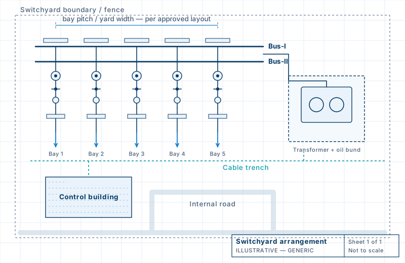
Generic switchyard arrangement plan with five bays, transformer and control building
Generic illustration of a switchyard arrangement plan.

Section 01

Scope and design basis

Electrical detailed engineering is the stage at which a tender or basic design becomes a set of drawings and calculations that suppliers and site teams can build from. CoreGrid prepares AIS and GIS substation electrical design for AC voltages up to 765 kV, whether the work is a greenfield switchyard, a pooling substation for a renewable plant, a BESS connection or an extension to an existing station, as each package defines.

The design basis is assembled from the project’s own documents: the single-line diagram and utility criteria; substation voltage, bus scheme and the number and type of bays; fault levels; insulation levels and statutory safety clearances; site and equipment constraints; relay scheme interfaces; any available general arrangement and technical specification; manufacturers’ guaranteed technical particulars (GTP) and drawings; soil information where earthing or foundations depend on it; and the master deliverable list (MDL).

Where an input is missing we say so, record the assumption we propose and ask the client to confirm it. Nothing is silently assumed. Because the electrical design drives civil and structural work, loads, levels and positions are passed to those disciplines as controlled interface data rather than informally.

Inputs the design depends on

InputWhy it matters
Single-line diagram and utility criteriaDefines the bus scheme, bays and ratings
Fault levels and insulation levelsDrive conductor, earthing and clearance design
Technical specification and MDLSet deliverables, formats and codes
Vendor GTP and drawingsFix dimensions, weights and terminal loads
Soil resistivity dataNeeded for earth grid and foundations
Site layout and constraintsLimit arrangement, routes and access

Section 02

Primary electrical layouts and drawings

Primary drawings fix how the switchyard is arranged and connected. The single-line diagram (SLD) shows the bus scheme, bays, transformers, line entries and ratings. The electrical key diagram (EKD) is a project-specific diagram whose content and format follow the client’s specification. The switchyard general arrangement places the equipment on the site with plan and sectional views, so that bus levels, clearances and connections can be checked.

From these we develop the plot plan, equipment mounting and termination interfaces, bus connection arrangements (strain, flexible or rigid as specified), line and bus terminations, transformer and reactor interfaces, ground connection points and the interfaces between equipment and supporting structures. Line, bus and equipment clearances are checked against the project criteria using approved vendor dimensions, and the drawings carry an electrical legend so each symbol and tag is defined.

Diagrams

  • System SLD, bus arrangement and bay list
  • Electrical key diagram (EKD), project-specific
  • Primary scheme and electrical legend

Layouts

  • AIS/GIS switchyard general arrangement and plot plan
  • Plans, sections and elevations
  • Cross-sectional layouts per bay
  • Equipment arrangement and clearances

Interfaces and details

  • Equipment mounting and termination interface
  • Bus connections: strain, flexible, insulating
  • Line entry arrangement
  • Ground connections
  • Equipment-structure interfaces

Section 03

Conductor and busbar calculations

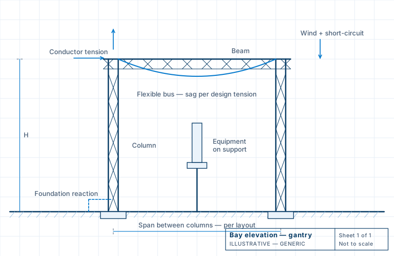
Conductors and busbars are selected for continuous current, operating temperature and fault withstand, with the standards and margins recorded. For flexible buses the sag-tension calculation fixes how the conductor hangs and what tension it passes to gantries and equipment terminals under the specified temperature and wind conditions.

We keep two things separate that are often confused. The system short-circuit level is an input, supplied by the client or from a system study. The mechanical effect of that current on conductors, spacers, insulators, terminals, equipment and supports is a calculation we prepare, and its results become loads for structure and foundation design. Spacer and insulator spacing checks and conductor clearances under the specified loading complete the group.

Illustrative gantry elevation with flexible bus and load arrows
Loads from conductors, wind and short-circuit forces pass to gantries and foundations. Generic illustration.

Conductor selection

  • Busbar and conductor sizing
  • Continuous current and temperature rise
  • Fault withstand

Mechanical checks

  • Flexible bus sag-tension
  • Short-circuit force on bus, terminals, equipment and supports
  • Spacer and insulator design checks

Clearance checks

  • Conductor tension and clearance under specified loads
  • Insulator and fitting interface loads
  • Loads passed to civil design

Section 04

Grounding and lightning protection

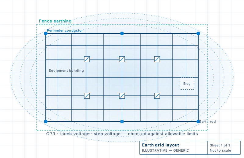
Illustrative earth grid layout with perimeter conductor, mesh, rods and potential contours
Earth grid with equipment bonding and perimeter conductor. Generic illustration.

Earthing design starts from measured soil resistivity and the fault current and duration the grid must carry. We develop the grid topology, size conductors and electrodes, and calculate grid resistance, ground potential rise (GPR) and the step and touch voltages against the allowable limits set by the project criteria. The earth grid layout and equipment bonding details turn the result into drawings that can be installed.

For non-uniform or multi-layer soil we model the grid in SES-CDEGS. Direct stroke lightning protection (DSLP) is handled alongside: shielding calculations by the project’s chosen method, a layout of masts and shield wires with heights and coverage, and the surge arrester and insulation coordination inputs. We do not promise a target resistance or a safety outcome before the calculation has been completed against the project’s criteria. Where soil data are poor or incomplete, we say so and record the assumption.

Section 05

Equipment sizing and selection

Equipment ratings are selected or checked against the single-line diagram, fault level, insulation level and duty of each bay. We prepare selection and rating checks for current transformers, CVTs and voltage transformers (ratios, classes, burdens and cores), surge arresters, circuit breakers, disconnectors and earth switches, and the interfaces of power transformers and shunt reactors, including neutral grounding resistor (NGR) sizing where in scope.

Scrutiny of manufacturers’ GTP and drawings is part of the same work, so that deviations from the specification are raised before drawings are issued and before equipment is manufactured.

  • CT, CVT/PT ratio, class, burden and core selection
  • Surge arrester selection and insulation coordination inputs
  • Circuit breaker, disconnector and earth switch ratings
  • Power transformer and reactor rating interfaces
  • NGR sizing, where in scope
  • OEM GTP and vendor drawing scrutiny

Section 06

Protection, control and SCADA interfaces

Protection and control work falls into three levels that are often confused. We are clear in each proposal which one is included.

Interface coordination covers control room layouts and interfaces, interlocking philosophy, relay and SCADA input/output interfaces and signal lists, prepared where the contract includes them. Protection and control schematics follow the client’s scheme and the panel supplier’s design when they are in scope. Relay logic programming, SCADA integration and commissioning are carried out by the panel and SCADA suppliers; we review their documents and support commissioning where contracted.

  • Control room and panel interface layouts
  • Interlocking and control philosophy, where assigned
  • Relay and SCADA I/O interface lists
  • Protection and control interface diagrams
  • Review of supplier schemes and SCADA documents

Section 07

Station auxiliary AC and DC systems

Auxiliary systems keep a substation controllable and safe. We prepare the AC auxiliary (LTAC) single-line diagram and load list, the DC system single-line diagram and load schedule, and the sizing of the station battery and battery charger from duty cycles, DC loads and autonomy periods specified by the client. Distribution boards (ACDB and DCDB) and panel interfaces are defined so that panel suppliers can work from agreed data.

Cable work includes sizing and voltage drop, routing and the trench and tray interface with civil design, the cable schedule and block diagrams. DG set and UPS interfaces are designed when the project includes them and provides the inputs.

LV AC and DC

  • LTAC SLD and load list
  • DC SLD and duty-cycle schedule
  • Battery sizing
  • Charger sizing
  • ACDB / DCDB requirements

Cables

  • Cable sizing and voltage drop
  • Cable schedule
  • Cable block diagrams
  • Trench, tray and routing interface

Section 08

Illumination design

Illumination design covers indoor and outdoor yard lighting: the calculation of illuminance against the project criteria, usually in DIALux evo, fixture positions and mounting heights, normal and emergency lighting circuits, and coordination with structures, equipment and cable routes. Emergency lighting is provided to the extent the project specifies. Photometric data come from the fixture manufacturer, and results are stated against the data used.

Section 09

Power-system studies

Power-system studies are offered by scope rather than excluded. Short-circuit, load flow, reactive power, harmonic and insulation coordination studies are prepared or reviewed as each project commissions them, using the client’s system data; earthing studies are prepared directly. Each proposal states the basis of every study.

  • Short-circuit study
  • Load flow and reactive power, by scope
  • Insulation coordination, by scope
  • Harmonic analysis, by scope
  • Earthing study, including SES-CDEGS

Engineering studies and their basis

Section 10

Electrical engineering by infrastructure type

InfrastructureElectrical focus
AIS/GIS substationsBus schemes, yard and hall layouts, SCF, earthing, DSLP, equipment ratings, auxiliary systems
Solar, wind and hybrid plantsCollection networks, plant SLDs, inverter and transformer interfaces, plant earthing, evacuation scheme
Pooling substationsCollector bay scheme, pooling transformers, metering, utility protection and SCADA interfaces
Battery energy storageSizing basis, PCS and transformer interfaces, auxiliaries, protection, EMS/SCADA interface
Transmission linesConductor selection, losses and corona, clearances, line entries into substations
HVDC stationsAC switchyard and filter yard layouts, converter transformer yard interfaces, station earthing

Section 11

Drawings, studies and documentation

What a typical electrical package can include. The contract and MDL decide what a given project contains.

DrawingsCalculationsDocuments
  • SLD and EKD
  • Switchyard GA, plan and sections
  • Earthing and DSLP layouts
  • Equipment interface drawings
  • Lighting layouts
  • LTAC and DC diagrams
  • Layouts and details
  • Conductor and busbar sizing
  • Short-circuit force
  • Flexible bus sag-tension
  • Earthing and lightning
  • Battery and charger
  • Cable sizing
  • Lighting
  • Transformer and auxiliary interfaces, when scoped
  • Design criteria reports and assumptions
  • Technical specifications
  • Master deliverable list (MDL)
  • GTP review sheets
  • BOQ and quantity take-off
  • Cable and signal schedules
  • Comment resolution sheets (CRS)
  • Revision register and transmittals

Open the electrical deliverables library

Section 13

Example work packages

Earthing grid design package

A calculation and drawing set for the earth grid and its connections, prepared from soil data and fault duty.

Inputs
Soil resistivity data, fault current and duration, layout and fence extent
Analysis
Grid sizing, GPR, step and touch voltage checks against project limits
Drawings
Earth mat layout, risers, equipment bonding details

Battery and DC system design

Sizing and arrangement of the station DC supply from the load schedule and duty cycle the client specifies.

Inputs
DC load list, duty cycle, autonomy and design margins
Analysis
Battery and charger sizing, DC load schedule
Drawings
DC single-line diagram and DCDB interface

Busbar and SCF package

Conductor and bus design with the mechanical effects of short-circuit current, giving loads for civil design.

Inputs
Fault level, span and layout, conductor and fitting data
Analysis
Conductor sizing, sag-tension, short-circuit force on bus, terminals and supports
Drawings
Bus arrangement and connection details

Switchyard arrangement package

The general arrangement and sections for the yard, coordinated with civil, cable and earthing drawings.

Inputs
SLD, bay list, equipment dimensions, site constraints
Analysis
Clearance and level checks, interface data to civil
Drawings
GA plan, bay sections, equipment placement

Potential deliverables, not guaranteed scope. Each item above is something CoreGrid can prepare where a project calls for it. A given contract includes only what its specification and MDL list. Examples are described in general terms and contain no project data.

Share your SLD, technical specification or MDL for an engineering proposal

Send us the tender extract, single-line diagram, master deliverable list or the specific calculation you need. We will confirm scope, inputs and a realistic submission sequence before any work starts.